9 The network layer
Chapter 8 rested on an assumption it never justified: That a packet can travel from your machine to any other machine on Earth. Making that true is the network layer’s job - carrying packets across many networks, router by router, using IP addresses. Its core idea: The network layer moves packets between hosts across networks, choosing a path one router at a time. By the end of this chapter you can read an IP address like a native, compute which network a host belongs to, explain how your laptop got its address in the first place, and account for the small miracle that your whole household hides behind a single public address.
9.1 Routing packets, hop by hop
What distinguishes this layer from the ones above? Transport ran only on the end machines; the network layer runs in every router along the way. It moves packets host to host, possibly across many separate networks, and its main protocols are IPv4, IPv6 and the helper ICMP. Every router does two conceptually different jobs, and separating them is half the understanding:
Definition 9.1 (Forwarding and routing) Forwarding is the fast, local action: Move an arriving packet to the right outgoing link (the data plane) - it happens per packet, in nanoseconds. Routing is the slower, network-wide task: Work out which paths the forwarding tables should hold (the control plane) - it runs in the background, keeping the tables correct.

The internet is a datagram network: No call is set up first; each packet is routed independently, based on its destination address, and routing is dynamic - if a link fails, later packets simply take another way. (Peek at your own machine’s table with route print or netstat -r.) No single router knows the whole path; each knows only the next hop towards the destination - and that is enough. The choice is made against a small forwarding table: Rows pair a destination network with an outgoing link or neighbour, the router picks the most specific matching row, and a final row 0.0.0.0/0 - the default - catches everything not listed. Your home router has exactly one of those, pointing at your ISP.
Who fills the tables? Routing algorithms, in two classic families: Link-state, where every router learns the whole map and computes shortest paths itself (Dijkstra), and distance-vector, where each router knows only its neighbours’ distances and estimates improve as neighbours share updates. Both converge on shortest paths; they differ in how much each router must know. Across the whole internet, though, no single computation runs: The net is divided into autonomous systems (AS), each running its own internal routing, while BGP - the Border Gateway Protocol - exchanges reachability between them, shaped as much by business relationships as by distance. Routing is thus two-level: Within an AS, fast and technical; between ASes, policy.
Two more facts complete the layer’s character. First, routers can fall behind: Each outgoing link has a buffer - a queue - of waiting packets; if packets arrive faster than the link drains, the queue grows, and when the buffer is full, further packets are dropped. This is precisely the loss TCP detects and reacts to (Chapter 8); the network layer itself makes no promise to deliver. Second, the packet’s own header: An IPv4 datagram carries version, header length, a TTL, a protocol field, checksum, and the source and destination IP addresses, followed by the transport segment as data. The TTL (time-to-live) drops by one at each router and the packet is discarded at zero - a safeguard against loops, and, as Section 9.4 shows, the trick behind traceroute. And because different links accept different maximum packet sizes (each link has an MTU, its largest frame), a datagram too big for the next link is fragmented into pieces that the receiving host reassembles - costly enough that senders usually discover the smallest MTU on the path and stay under it.
The mechanics are worth one close look. Every IPv4 datagram carries an identification number; when a router must fragment, every fragment keeps that same number, plus a fragment offset saying where its bytes sit in the original, plus a flag announcing whether more fragments follow. Two consequences fall out of this design. First, fragments are reassembled only at the final destination, never by routers along the way - each fragment is routed independently, possibly along different paths, so no router in the middle can be sure of seeing them all. Second, the design is fragile by arithmetic: Lose any one fragment and the destination can never rebuild the datagram, so the whole datagram is lost and - if TCP is above - retransmitted in full. One lost fragment costs the entire packet. That is why senders prefer to discover the smallest MTU on the path and stay under it, and why a datagram can even be marked “don’t fragment”: Better an honest ICMP error than a silent, expensive gamble.
(Dostálek & Kabelová, 2006, ch. 5)
9.2 IP addresses
Definition 9.2 (IPv4 address) An IPv4 address is a 32-bit number identifying one host or router interface (adapter), written in dotted decimal as four bytes of 0–255: 10.11.1.21 is 00001010\;00001011\;00000001\;00010101. A machine with several adapters has several addresses.
Run ipconfig (Windows) or ifconfig (macOS/Linux) and read your own. Note the Chapter 2 payoff: An octet stops at 255 because it is one byte - and the whole space holds 2^{32} \approx 4.3 billion addresses, a number Chapter 2’s table already flagged as “the IPv4 address space”.
Historically the space was carved into fixed classes: A, B and C for ordinary hosts (differing in how many bits were network part), D for multicast, E reserved - plus 127.* as loopback, a host talking to itself. Fixed classes wasted huge ranges, which is why CIDR (Section 9.3) replaced them. Some ranges were also set aside never to appear on the public internet: Private addresses such as 10.* and 192.168.* are used inside a LAN only and are not routable - routers drop them - which is why your laptop and your neighbour’s can both be 192.168.0.10: Each is purely local, and NAT (Section 9.5) is what lets them reach the world. Delivery itself comes in three flavours: Unicast, one sender to one receiver - the normal case; broadcast, one sender to every host on the local network; multicast, one sender to a subscribed group (the class-D addresses) - ideal for live streams, where the network duplicates as needed.
Even with private ranges and NAT, 32 bits ran out. IPv6 answers with 128 bits - 2^{128}, an effectively unlimited supply - written as eight groups of hex digits, with runs of zero groups abbreviated by :: - so 2001:db8::1 is short for 2001:0db8:0000:…:0001; it also simplifies the header and removes the need for NAT. The transition is gradual coexistence, not a switch-over: IPv4 and IPv6 run side by side, and most devices speak both.
9.3 Subnets and CIDR
Addresses are not random; they are grouped into networks, and the grouping is pure Chapter-2 bit arithmetic.
Definition 9.3 (Netmask, CIDR) A netmask splits an address into a network prefix and a host part: It is a bit-mask of 1s over the prefix and 0s over the host bits, and address AND netmask = the network the host belongs to. Two hosts can talk directly only if they share a network; otherwise the packet goes to a router. CIDR (Classless Inter-Domain Routing) lets the prefix be any length, written address/n - a bigger n means more prefix bits, fewer host bits, a smaller network.
Example 9.1 (Which network?) Host 10.21.26.184 with mask 255.255.252.0 (a /22). Only the third octet is interesting - the mask is 252 there. Host third octet: 26 = 0001\,1010. Mask: 252 = 1111\,1100. AND them: 0001\,1000 = 24. The host therefore belongs to network 10.21.24.0/22 - and every address from 10.21.24.0 to 10.21.27.255 is on that same network. The AND operation is Chapter 2’s masking, doing real work.

10.21.24.0/22 of Example 9.1.
The prefix length also fixes how big a network is: With a /n prefix, 32-n bits remain for hosts, giving 2^{32-n} addresses - minus two, for the network and broadcast addresses. A /24 has 2^8 = 256 addresses and thus 254 usable hosts; a /16 is a big network, a /30 a tiny one, handy for point-to-point links. (In Example 9.1: 32-22 = 10 host bits, so 1024 addresses, 1022 usable.)
Host 172.16.5.130 has the mask 255.255.255.128 (a /25). Which network does it belong to, what address range does that network span, and how many usable hosts does it hold? Work as in Example 9.1 - only the fourth octet is interesting.
Solution. Fourth octet AND mask octet, bit by bit:
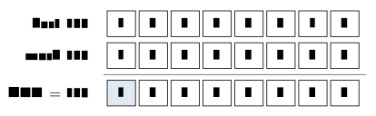
Network: 172.16.5.128/25, spanning 172.16.5.128–.255. Host bits: 32-25 = 7 \Rightarrow 2^7 = 128 addresses, 126 usable (network and broadcast subtracted). Only the mask’s single 1-bit survives the AND - everything under the mask’s zeros is host part.
9.4 Getting an address, and reading the network
In practice you do not type addresses by hand - a server hands you one. A DHCP server holds a pool of addresses and leases one to your machine dynamically when you join, the machine identifying itself by its MAC address in the first request (Chapter 10’s hardware address, making an early appearance). The lease is arranged in a four-step exchange with a friendly acronym, DORA: The client Discovers (broadcast - it has no address yet, so it must shout to the whole local network), the server Offers an address, the client Requests it, the server Acknowledges. Usefully, DHCP delivers more than the address: Typically also the gateway (your router) and a DNS server - everything needed to start using the network.
Diagnosis is the province of ICMP, a helper protocol used by hosts, routers and gateways to report problems: It carries error messages and echo request/reply, riding inside IP datagrams while belonging to the network layer - it is how the network talks about itself. The types to know: 8/0, echo request and reply; 3, destination unreachable; 11, time exceeded (TTL reached zero). Type 8 is the basis of ping: Send an echo, await the reply, confirm reachability and measure the round-trip time - remembering that no reply does not always mean “down”, since some hosts and firewalls ignore pings.
Example 9.2 (How traceroute really works) Type 11 enables something cleverer. traceroute reveals every router on a path by letting packets expire on purpose: Send a packet with TTL = 1 - the first router decrements it to zero, drops it, and returns an ICMP “time exceeded”, revealing itself; send TTL = 2 and the second router reports back; and so on, one hop per step, until the destination itself replies. The path you watched in Chapter 6 was built from exactly these deliberately-expiring packets - the TTL field, a loop safeguard by design, repurposed as a measuring tape.
One look ahead before the last section: IP picks the next hop, but the link below needs a hardware address. Each interface also carries a fixed MAC address, and to send to a neighbour a host maps IP to MAC using ARP - asking the local network “who has this IP? tell me your MAC.” That hand-off across one physical hop is Chapter 10, in full.
9.5 NAT: One address for a whole network
From the internet’s point of view, your whole home is a single address. Devices inside use private addresses (say 10.0.0.*); the router holds one public address from the ISP and rewrites packets - outgoing, it swaps the private source for its public one; incoming, it swaps back. Network Address Translation lets many devices share one public address, and it is a big reason IPv4 has lasted so long past its exhaustion.
If everyone leaves the house wearing the same public address, how do replies find their way back? Through a translation table keyed by ports: Inside 10.0.0.1:3345 might map to public port 5001, inside 10.0.0.2:3345 - same private port, different device - to public port 5002; replies to each public port are rewritten back to the right inside socket. (Ports, once again, doing addressing work - Definition 8.1 stretched one layer down.) The hiding cuts both ways: Many devices on one address, renumber-free ISP changes, and inside devices not directly reachable - a rough security benefit - but also the well-known traversal problem: An outside client cannot reach an inside server by its private address, worked around with port forwarding, UPnP, or a relay in the middle, Skype-style. Curious what the world sees? Any “what is my IP” service shows the public address your NAT presents.
Before Lecture 10 (The link layer). Read the Module 10 chapter in the textbook (Readings.xlsx for the pages). Try this: Run ipconfig/ifconfig and find your IP address, netmask and gateway - then compute, by Example 9.1’s method, which network you are on. And think about the gap this chapter left open: IP gets a packet to the next router - but how is it physically handed across that one link, and how is the right neighbour found?
9.6 Summary
The network layer routes packets host to host: Forwarding is the per-packet reflex, routing the background planning (Definition 9.1); the internet is a datagram network where each router knows only the next hop, chosen by most-specific match in a forwarding table filled by link-state or distance-vector algorithms inside an AS and by policy-driven BGP between them - and where full queues drop packets, the loss TCP feels. IPv4 addresses are 32 bits in dotted decimal (Definition 9.2), with private and reserved ranges, three delivery modes, and IPv6’s 128 bits ending the shortage. A netmask ANDs an address into its network (Definition 9.3, Example 9.1), CIDR makes the split flexible, and 2^{32-n} counts the hosts. DHCP leases addresses through DORA; ICMP diagnoses - echo behind ping, expiring TTLs behind traceroute (Example 9.2). And NAT shares one public address through a port-keyed table, hiding the inside for better and worse. One gap remains - the single physical hop - and it is next week’s whole subject.
Interactive checks
A round of quick interactive drills - instant feedback, all in your browser, nothing recorded. Every task has a show-solution button; clicking it straight away is no fun.
Self-check
Exercise 9.1 (Forwarding versus routing) Forwarding versus routing: One sentence each, naming the plane, the timescale, and where each runs.
Exercise 9.2 (Subnet computation) Which network does host 192.168.13.77 with mask 255.255.255.192 (/26) belong to, and how many usable hosts does that network hold?
Exercise 9.3 (The DHCP handshake) Name the four DHCP steps in order, and explain why the first one must be a broadcast.
Exercise 9.4 (How traceroute works) Explain, in terms of one specific IP header field and one specific ICMP type, how traceroute discovers the third router on a path.
Exercise 9.5 (NAT port translation) Two laptops behind the same NAT both open connections from their private port 4000. How does the router keep the replies apart?
- Forwarding: Data plane, nanoseconds per packet, in every router - move the packet to the right outgoing link. Routing: Control plane, background timescale, network-wide - compute which paths the tables should hold. (2) Fourth octet 77 = 0100\,1101, mask 192 = 1100\,0000; AND = 0100\,0000 = 64, so network
192.168.13.64/26; host bits 32-26 = 6 \Rightarrow 2^6 = 64 addresses, 62 usable. (3) Discover, Offer, Request, Acknowledge; the client has no IP address yet, so it cannot address anyone directly and must broadcast to the whole local network. (4) It sends a packet with the TTL field set to 3; the third router decrements it to zero, discards the packet, and returns ICMP type 11 “time exceeded” - revealing its own address. (5) Its translation table maps each inside socket to a different public port (e.g. 4000→5001 and 4000→5002); replies arriving at each public port are rewritten back to the matching private address and port.
Packets now cross the world: Addressed by IP, routed hop by hop, helped along by DHCP, ICMP and NAT. One gap remains, left open deliberately: Each hop is one physical link, and crossing it - finding the right neighbour and handing the frame over - is a job of its own. Chapter 10 closes the stack with exactly that: MAC addresses, ARP, Ethernet and Wi-Fi.