10 The link layer
Chapter 9 left one gap open on purpose: IP gets a packet to the next router - but each hop is one physical link, and crossing it, including finding the right neighbour on it, is a job of its own. That job is the link layer: Moving a frame across a single link, between directly connected nodes. Its core idea completes the stack: The network layer plans the whole route; the link layer carries the frame across each single hop along it. With this chapter, the descent that began at the application layer reaches the wire - and the course’s networking story closes with one complete journey, keypress to rendered page.
10.1 One hop: Nodes, links, frames
The vocabulary first. Nodes are hosts, routers and switches; links are the channels connecting neighbouring nodes; and the link layer moves a frame over one link, node to node. Where the network layer sees the whole path A–B–C, the link layer only ever handles one hop, like A–B - and each hop along a route may use a completely different technology. The lecture’s analogy travels well: A trip from Halden to Trondheim by train, then plane, then bus - each leg its own vehicle - just as one network path may run Ethernet, then fibre, then Wi-Fi, the IP packet riding inside whatever frame each link uses.
Whatever the technology, the layer offers the same handful of services, each in some form: Framing (wrap the datagram in a header and trailer), link access (decide who may use a shared medium - Section 10.3), reliable delivery between neighbours (often skipped on low-error links), flow control (do not outrun the neighbour), error detection (spot corrupted bits) and sometimes error correction (fix a few without resending). The mix is technology-dependent: On a clean fibre link reliability is barely needed; on noisy Wi-Fi it matters greatly. And almost all of it runs in one specific piece of hardware - the network adapter, or NIC, which builds and reads frames, checks for errors and controls medium access, largely independent of the CPU. The frame itself is simple: A header carrying the link addresses and a type, the IP datagram as payload, and a trailer carrying an error check.
10.2 Link addresses and ARP
The header’s addresses are not IP addresses.
Definition 10.1 (MAC address) A MAC address is a 48-bit hardware address - twelve hex digits - baked into each network adapter, naming this adapter on the local link. The IEEE assigns each manufacturer a prefix (the OUI); the maker fills in the rest, so every adapter worldwide is unique. See yours with ipconfig /all (“physical address”).
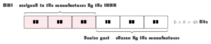
3C:5A:B4:1F:9E:02): The first three bytes are the manufacturer’s IEEE-assigned prefix (OUI), the last three the manufacturer’s own numbering - flat, with no location meaning.
Why a second address system, when we already have IP? Because the two work at different scales, and the contrast is exam material: The IP address lives at the network layer, has end-to-end scope across the internet, and is hierarchical - network part plus host part, like a postal address that encodes where in the world you are. The MAC address lives at the link layer, has scope of one local link only, and is flat - no location meaning at all, like a person’s ID number. The consequence to remember: A packet keeps its IP addresses end-to-end but gets a new MAC pair on every hop.
So a sender knowing only a neighbour’s IP must first find the matching MAC - Chapter 9’s look-ahead, now in full.
Definition 10.2 (ARP) The Address Resolution Protocol maps a neighbour’s IP address to its MAC address. Every node keeps an ARP cache of known IP→MAC mappings; entries time out so the cache stays current. ARP only ever works within one link - it finds local neighbours, never distant hosts.
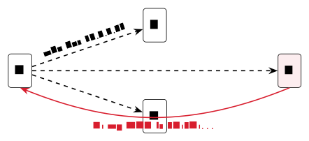
Example 10.1 (ARP in action) Host A wants to send to neighbour B but knows only B’s IP. A broadcasts to everyone on the link: “who has IP so-and-so? Tell me your MAC.” Every node hears it; only B, who owns that IP, replies with its hardware address. A caches the answer and sends the frame. Run arp -a and you are looking at your own machine’s cache of exactly these learned answers.
What does the cache actually look like? Exactly what the theory predicts. On a Windows machine, arp -a prints it:
C:\> arp -a

Interface: 10.0.0.5 --- 0x8
  Internet Address      Physical Address      Type
  10.0.0.1              a0-11-75-2c-00-1b     dynamic
  10.0.0.23             3c-5a-b4-1f-9e-02     dynamic
  10.0.0.255            ff-ff-ff-ff-ff-ff     static
Read it line by line with the chapter’s vocabulary. 10.0.0.1 is the gateway - the router, learned by an ARP exchange like Example 10.1 and marked dynamic: It was answered, cached, and will time out. 10.0.0.23 is a neighbour this machine recently talked to - and its first three bytes, 3c-5a-b4, are the OUI of Figure 10.1. The last line is no mystery either: ff-ff-ff-ff-ff-ff is the broadcast MAC - all 48 bits set - the “everyone on this link” address that ARP’s own question is sent to; it is static because it never needs to be learned. The cache, in short, is the protocol’s memory: Every entry is a question that did not have to be asked twice.
The protocol has two variants that answer questions nobody appears to have asked. In proxy ARP, a router answers an ARP request on behalf of a host on another network: It replies with its own MAC address, quietly collects the frames, and forwards them onward - the sender believes the destination is a local neighbour and never learns otherwise. Once a common way to join networks without configuring routes, it survives today in corners of Wi-Fi and virtualisation setups. In gratuitous ARP, a host broadcasts an ARP request for its own IP address at start-up. Useful twice over: If anyone answers, the address is already taken - duplicate-IP detection for free - and if nobody does, every listening neighbour has just refreshed its cache with the newcomer’s mapping, which is exactly how a machine with a freshly changed network card announces itself. Both tricks work because ARP trusts whatever it hears on the link - a generosity that security people, who know it as the basis of ARP spoofing, regard with less affection.
(Dostálek & Kabelová, 2006, ch. 5)
10.3 Sharing the medium
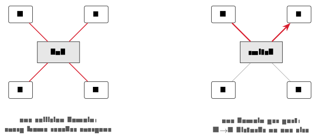
ARP’s broadcast worked only because the link is shared - which raises the layer’s classic problem. On a point-to-point link (one sender, one receiver) there is no contest; on a broadcast medium - classic Ethernet on one wire, Wi-Fi in the air - many nodes share one channel, and two simultaneous transmissions collide: Their signals overlap and both are lost. The link layer needs an access rule, and the rules fall into three families.
Channel partitioning gives each node a fixed slice so collisions never happen: TDMA divides time into slots, FDMA divides the spectrum into bands, CDMA separates senders by code. Excellent for steady traffic (cellular voice); wasteful for bursty traffic, since a silent node still holds its slice. Taking turns lets exactly one node send at a time: A circulating token (Token Ring) or a polling controller - orderly and collision-free by design, but the coordination adds delay and a single point of failure. Random access embraces the risk:
Definition 10.3 (CSMA/CD) Carrier Sense Multiple Access with Collision Detection: (1) carrier sense - listen; if the medium is busy, wait; (2) send when it is free; (3) collision detect - if signals clash, stop at once; (4) wait a random back-off time, then try again. The random back-off makes a repeat collision unlikely. This is exactly how classic Ethernet shared a wire.
Internet traffic is bursty (Chapter 6 made the point for packet switching; it returns here), which is why random access usually won. Sharing has a cost either way: A shared medium splits its capacity among all active users - one node alone gets the full rate; many nodes each get a fraction, with collisions wasting time on top. That is why a crowded café Wi-Fi feels slow even with a fast line behind it: The access point’s capacity is divided among every connected device.
10.4 Ethernet and switches
The most successful wired design tamed the sharing problem so thoroughly it took over the LAN. Ethernet (IEEE 802.3) was the first widely-used LAN technology and remains the wired standard; its character is minimalist - connectionless (no handshake before a frame) and unreliable (no acknowledgements; recovery is left to TCP far above) - and it originally shared one wire with CSMA/CD. It kept pace for decades: From 10 Mbit/s shared coax through Fast Ethernet to today’s switched gigabit and beyond, while its frame stayed remarkably stable: Preamble, destination MAC, source MAC, a type field naming the protocol inside (usually IP), the payload, and a CRC trailer that lets the receiver detect a corrupted frame and drop it.

What modernised Ethernet was a box. Early installations joined machines through a hub - a physical-layer repeater that blindly copies every bit to all ports, making the whole network one big collision domain. The switch replaced it: A link-layer device that reads each frame’s destination MAC and forwards it only to the right port, so each port becomes its own collision domain and everyone can send at once. Best of all, a switch configures itself:
Example 10.2 (Switch self-learning) A switch keeps a table of MAC → port entries with timestamps - and fills it just by watching. When a frame arrives, the switch learns that the sender’s MAC lives on that port. Destination unknown? It floods the frame out of all ports, then learns from the reply. No configuration needed: Plug and play, the network learned as frames flow.
A freshly powered switch has an empty table. Then: (1) host A on port 1 sends a frame to host B; (2) B, on port 4, replies to A; (3) A sends to B again. For each step: What does the switch learn, and out of which port(s) does the frame go?
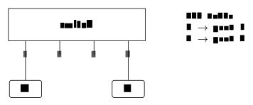
Solution. (1) Learns A → port 1 from the source address; destination B unknown \Rightarrow floods out of all ports except 1. (2) Learns B → port 4; destination A is in the table \Rightarrow forwards to port 1 only. (3) Nothing new to learn; B is known \Rightarrow forwards to port 4 only. After one round trip the flooding stops - the table shown above has built itself.
Scaled up, this is how an institution’s network is built: Switches knit the internal LAN together by MAC, and a single router connects the whole subnet to the rest of the internet by IP. The three boxes are best kept apart by layer - all of them store and forward, at different levels: A hub works at the physical layer, reads nothing, isolates nothing; a switch works at the link layer, reads MAC addresses, isolates traffic, and is plug-and-play; a router works at the network layer, reads IP addresses, isolates traffic, and needs configuration. Switch = within a LAN by MAC; router = between networks by IP.
10.5 Wireless - and the whole journey
Wired LANs solved sharing with switches; wireless cannot, because there is no wire to switch - so Wi-Fi shares the air, carefully. Wi-Fi (IEEE 802.11) is a family of standards - a/b/g/n/ac/ax…, with Wi-Fi 6 (802.11ax) and Wi-Fi 7 (802.11be) the newest - operating either through an access point (AP) or ad-hoc, device to device. All devices on an AP share its capacity: The cost-of-sharing paragraph, made wireless.
One physical fact forces a different access rule: A radio cannot listen while transmitting, so it cannot reliably detect its own collisions. Wi-Fi therefore uses CSMA/CA - collision avoidance: Sense the medium, wait a random back-off, then send - trading Ethernet’s simple detect-and-retry for careful avoidance. Radio adds further quirks no cable has: Signal strength falls off rapidly with distance; walls and obstacles attenuate (frequency-dependently); reflections and other devices interfere - which is why Wi-Fi range and speed vary so much around a building, and why wired links stay the dependable choice. Wi-Fi has siblings tuned to other jobs: Bluetooth for a few metres (earbuds, peripherals), NFC for a few centimetres (tap-to-pay), Zigbee for low-power smart-home sensors, cellular 4G/5G for the wide area - all facing the same shared-air challenge with different range-power-speed trades.
An open medium also raises the security question directly: Radio travels through walls, so a neighbour or passer-by can pick up the signal. Modern Wi-Fi therefore encrypts the link with WPA2 or WPA3, so only devices knowing the password can read the traffic; an open, password-free network leaves everything readable - avoid sending anything sensitive over one. And remember the layering: HTTPS (Chapter 7) still protects each web page on top of the Wi-Fi encryption - two locks, different layers.
One shared service runs across every link technology: Catching corrupted bits. In increasing strength: A parity bit - one extra bit, catching any single flip, simple but weak; a checksum - a sum over the data, as UDP and TCP use (Chapter 8); and the CRC - a polynomial code in the Ethernet trailer that catches almost all real-world errors. This is the family Chapter 4’s ECC memory promised would “return in networking” - and the division of labour is tidy: Link-layer detection drops bad frames early; reliable delivery, where needed, is rebuilt by TCP far above.
Example 10.3 (One web request, end to end) Every layer of the last five chapters, in a single action. (1) DNS resolves the name to an IP address (Chapter 7). (2) TCP opens a connection to the server (Chapter 8). (3) IP chooses the route, hop by hop (Chapter 9). (4) ARP finds the next hop’s MAC, and the frame crosses the link (this chapter). (5) HTTP carries the page back, and the browser renders it (Chapter 7) - all of it, from the first keypress to the last pixel, as bits under conventions (Chapter 1). Application down to link and back: The whole networking module in one page load.
Before Lecture 11 (Repetition). Skim your notes from Lectures 1–10 and mark anything still unclear - next week’s session is built for exactly those marks. Try this: Run arp -a to see your machine’s ARP cache, and find your own MAC with ipconfig /all.
10.6 Summary
The link layer carries a frame across one hop, between directly connected nodes, in the adapter: Framing, access, error detection - the service mix varying with the medium. MAC addresses (Definition 10.1) are flat, 48-bit and local, where IP is hierarchical and end-to-end - so the IP addresses persist across a journey while the MAC pair changes at every hop, and ARP (Definition 10.2, Example 10.1) bridges the two by broadcast-and-reply on the local link. A shared medium needs an access rule - partitioning, taking turns, or random access, with CSMA/CD (Definition 10.3) the classic and bursty traffic its justification - and sharing always divides capacity. Ethernet plus self-learning switches (Example 10.2) dominate wired LANs, isolating collision domains port by port, with hub, switch and router cleanly separated by layer. Wi-Fi shares the air with CSMA/CA - it avoids collisions because it cannot detect them - secured by WPA2/WPA3; and parity, checksums and CRCs catch corrupted bits at every link, while TCP rebuilds reliability above. The stack is complete (Example 10.3); the two remaining chapters consolidate it.
Interactive checks
A round of quick interactive drills - instant feedback, all in your browser, nothing recorded. Every task has a show-solution button; clicking it straight away is no fun.
Self-check
Exercise 10.1 (Addresses along a path) A packet crosses four links from your laptop to a server. How many times do its IP addresses change, and how many times its MAC addresses? Why?
Exercise 10.2 (The ARP exchange) Describe the ARP exchange when host A first contacts neighbour B - who hears what, who answers, and what does A store?
Exercise 10.3 (CSMA/CA versus CSMA/CD) Why does Wi-Fi use CSMA/CA rather than Ethernet’s CSMA/CD? Name the physical constraint.
Exercise 10.4 (Hub, switch, router) Hub, switch, router: Give each device’s layer and what it reads - and say which of the three isolates collision domains.
Exercise 10.5 (Reliability and the CRC) Ethernet is “unreliable” by design. Where in the stack is reliability provided instead, and what does the Ethernet CRC contribute?
- The IP source and destination never change - zero times; the MAC pair changes on every hop - four times - because MAC addresses have only local, per-link scope. (2) A broadcasts “who has this IP?” to the whole link; every node hears it, but only B - the owner of the IP - replies with its MAC; A caches the IP→MAC mapping (with a timeout) and sends the frame. (3) A radio cannot listen while it transmits, so it cannot detect its own collisions; it must therefore avoid them - sense, random back-off, then send. (4) Hub: Physical layer, reads nothing; switch: Link layer, reads MAC addresses; router: Network layer, reads IP addresses. The switch isolates collision domains - each port becomes its own.
- Reliability lives in TCP at the transport layer (ACKs and retransmission); the CRC only detects a corrupted frame so it can be dropped early - detection below, recovery above.
The stack is complete: From a keypress through DNS, TCP, IP and ARP to a rendered page, every layer accounted for. What remains is to make it stick. Chapter 11 walks back through the whole course in five blocks, with quick checks in the exam’s own format - the place to find the gaps while there is still time to close them.